The Simplest Line Follower – Upgraded! [Updated]
April 22, 2012 41 Comments
Hello everybody!
Apologies for not writing for so long! Work has kept me really busy so I wasn’t able to do much till now.
Last week I finally got time to do a bit of work. I made my own PCB :). I wish I had learned this back in college. It have would saved me so much time. What PCBs did I make? The line follower circuit (Click me to open tutorial) I explained before. That design had two very irritating problems. Firstly the wires would keep breaking off and I would have to re-solder many times. Secondly, the cardboard mounts would keep bending.
The new robot uses very little wiring. None of the wires have been soldered. I have also replaced the mounts for the sensors. I will describe everything in today’s post.
Before we begin, you’ll need to know how to design and build your own PCBs. A friend of mine has written excellent, very well explained tutorials for this. He uses Eagle. I will try learning KiCad for you free software folks. I’m having trouble with it though (Do pop in a comment if you would like to help me out) . Here are the links to the tutorials:
I would suggest going over his circuit if you need some confidence. I made the line follower circuit for my first PCB. It’s simple too so you could try that as your first PCB.
Assuming you know how to make PCBs, here’s what you do. Make one main PCB for the L293D. You’ll need two other small PCBs to put the sensors. I’ve uploaded the eagle files containing my designs. You can download these from the Box.net widget on the right sidebar. Look for bruno-eagle-files.zip and LEDLDR-eagle-files.zip. I would suggest designing the PCB yourself for practice. Your design may be much better. I have a lot of inconsistencies in mine.
Here are photos of my PCBs:
The main L293D PCB:
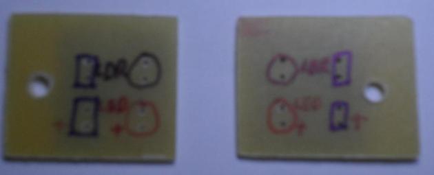
All that labelling was to make the soldering easier. However I messed up while using the lacquer spray. 😐 You’ll see the results of that shortly. Now here are the PCBs for the LED-LDR sensor:
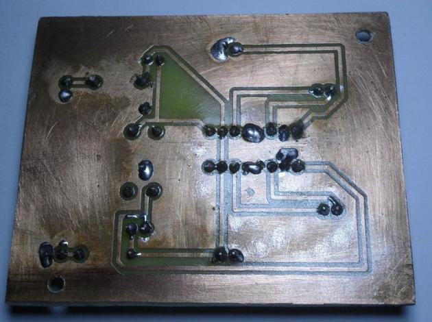
So those are the boards. Also remember to drill holes for the main PCB. I forgot to do this till the end. Drilling after soldering is a pain. Next step is to solder the components. Check all connections with a multimeter. At this point you can even check if the LEDs are lighting up and if the LDR sensors are working. Remember – do not plug in the chip till you have done this bit of testing. After you’ve checked that all the voltages are right, put a protective coat over the copper side of the PCB. I used lacquer spray. Unfortunately I forgot it is acetone based and made a mess of the labelling of the L293D PCB. Here is how it all looks now:
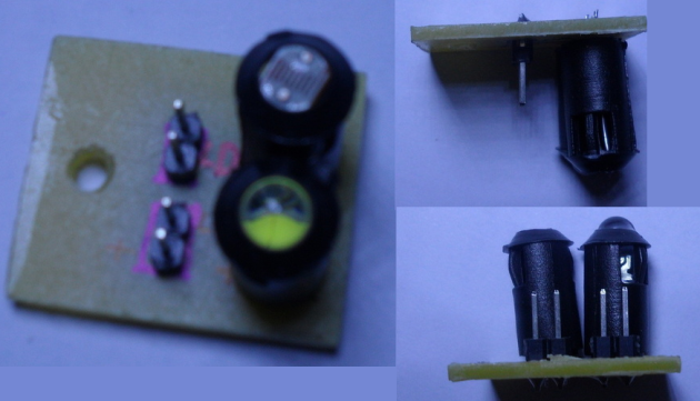
As you can see, I should have left a little more space at the edges. The copper in the photo is tarnished. It took a while for me to buy lacquer so this happened by then. A bit of sandpaper got it all cleaned up. My suggestion is to put the protective coating soon after you’re done soldering. Note that I have used berg pins instead of soldering the wires directly. Here is how I soldered the sensors:
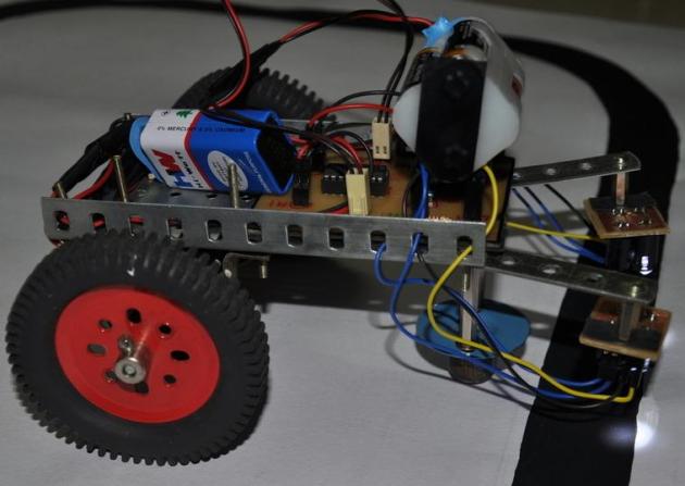
Now that the electronics is mostly done, lets move on to the chassis. I used the same mechano plate as last time. For the sensors, I also used a mechano part. Note a few differences in the photos you are going to see and the actual robot. The photos below shows the 4-hole part. I replaced this with a 5-hole one later. Also I moved the PCB up to the front as the wires weren’t long enough. Finally I had to change the wheels as this construction was very unstable. You’ll see the corrections in the last photo. For the connections, I used female jumper wires such as these:
Before fixing the PCBs to the base, make sure you put something to protect the copper side. We do have a coating but better be safe than sorry. I used pieces of cardboard.
The chassis:
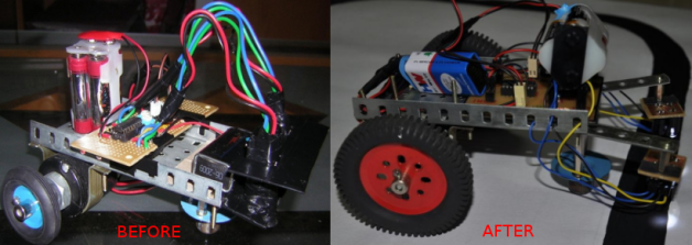
The corrected version. The sensor mounts are folded. I’ll explain this next. Notice how I used some screws to sort out the motor’s wires. I’ve kept these wires long as I’ll be using the same motors for other robots as well.
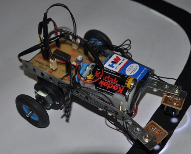
See how neat this is compared to the original robot? Finally here are a few photos of the complete robot.
Observe how the sensors have been mounted here. Metal mounts = no bending, if you’re careful enough of course. I found a big advantage of using these plates only after I completed the robot. You can fold these sensors under the main base. This further protects them from damage when you store the robot. This is what I mean:
Pretty neat isn’t it? Finally these plates also make adjusting the distance between the sensors a lot easier. With the cardboard mount, you’d have to replace it each time the width of the line changed. In the new robot’s case it’s very simple:
As indicated above, you can freely adjust both the plate as well as the PCB. Again, remember to protect the copper side with something like cardboard. Finally, connect the batteries and you’re good to go:
I used larger wheels so the robot was a bit too fast. (v = r x ω). I put the batteries at the front to slow it down. It slows down because the friction on the front castor wheel increases. If you use the small wheels like last time, keeping the batteries at the back should work. Another reason to keep the batteries ahead is that it makes the robot more stable. Unfortunately the wires I used were too short so the PCB had to go to the front and the battery space got pushed back. I’ll probably join two wires to increase the length when I get time.
So that is the new and improved line follower! Hope you like this little upgrade.
For my next activity, I will do the same upgrade for the table follower. We shifted to a new place last year and both robots, especially the table follower, were damaged in the process. The table follower’s mounts are broken. These new metal plates should make a more robust bot. I will also try to make it smaller by making smaller PCBs. I wasted a lot of space in this PCB as it was my first time.
I have also bought a bit of equipment. I will blog about it either during the week or on the weekend so stay tuned for details of my lab in progress 🙂
Please do tell me what you think in the comments below. I’m sure you will have much better ideas and I’d love to hear you out. Thanks for reading! 🙂
Update 1
I was able get longer jumper wires and reverted to the smaller wheels. I also used smaller beams for the sensors. Here is how my robot looks now.
I also changed the motors to 150RPM. I’ll be using the 200RPM motors for the table follower update. I should hopefully be done this weekend.
Update 2
In case you want to install Eagle on Fedora, I found instructions here: Installing Eagle 6 on Fedora 17.These instructions are for Fedora 17 (which is scheduled to release on 29th May 2012). If you are using Fedora 16, extract the files to /lib instead of /usr/lib.










I think you forgot to use ‘flux’ while soldering. Hence, the shoddy results 😛
I did use flux. I’m still no good at soldering 😦
can i get ur phone number bro? need to do a project on this?
You can ask your questions in the comments. I cannot share my phone number.
After proper soldering, clean the bare board with IP alcohol. removes all the flux and the board looks shiny
Thanks for the tip! 🙂
It looks really good. Less messy and more robust.
Thanks dude! 🙂
Its a great job dude .ur way of explaining the concept is very neat and simple too.keep up the good working.
Thank you! I’m glad you liked it 🙂 Can’t wait to get some free time to put up more tutorials.
Is there any chance to use 3 sensor in this technique without move on to micro controller.bcoz i want to include middle sensor also to keep the bot on the track some more accurately.
It *should* be possible but you will need to add extra logic (using basic gates and flip flops). Decide whether your design needs to be a combinational logic circuit or sequential. Then follow standard design methods.
In Motor driver circuit,the i\p pin 1 and 4 are grounded ,whereas 2&3 are given to 5v .it is clear ‘but i cant understand one thing that is the motors are enable only if both the i\ps from op amp are high .but how 4 i/p and 4o/p values are changes in combination like 0110,0010,0100,1001.they are connected to vcc and gnd then how the in value changes .please explain it my email id is madhan0994@gmail.com.
I’m not able to understand your question. I have written another tutorial about a more basic version of this robot. Check it out here (Click) This explains how the robot works in detail. The robot is an older version where I used a general purpose PCB and cardboard to mount sensors. The circuit and working is exactly the same. Do check it out. Maybe it will help.
In the limitted version of eagle there no pdf option under file print .I dont have laser printer at home so please help me to solve this problem .I want my pcb layout to convert in to pdf file.
You can go to File > Export > Image and save it as an image file.
Thank you for your all replies.
But in your tutorial you mentioned that exporting the layout as image file needs photograph to change its resolution thats why i am asking you about pdf file.
You could install a PDF printer in your system. I use a software called CutePDF. http://www.cutepdf.com/
BTW, I didn’t write the PCB etching tutorial. That website belongs to someone else.
Could you please upload the eagle project file of your bruono line follower .
I want your eagle project file of bruno lfr.could you please upload It for me.
It is there already. See the box.net flash_widget on the right side of the page (You need to have flash installed in your browser)
i am having opera v12.02 how to install flash player in it .because there is no box.net widget on the right side of page.\
I test ur circuit by connecting with bread board twice both the time ,the motor which is connected to pin 14 and 11 only rotates ,both led glows .the motor which is connected to the pin 3 and6 is not rotating .iam using 9v baterry .how to over come this.after verified the circuit only i am gng to move on to pcp.please kindly help me i checked the loose connections also ,so i hope you understand my trouple so please help me …
I checked every pins using multimeter.i am using the same l293dne ic.i am using v1 as 9v and v2 as 4v .
the following are the voltage value of each pin obtained in multimeter with respect to ground.
pin 1(en)=0v
pin 2(in1)=4v
pin3(out1)=0v
pin4(gnd)=0v
pin5(gnd)=0v
pin6(out2)=0v
pin7(in2)=0v
pin8=7.9v
pin9(en2)=3v
pin10(in3)=0v
pin11(out3)=0.53v
pin12(gnd)=0v
pin13(gnd)=ov
pin14(out4)=8v
pin15(in4)=4v
pin16=4v.
the motor connected to pin 11 and 14 rotates .but the other motor connected to pin 3 and 6 does not rotate.anable pin 1 is 0 .but another enable pin 9 is 3v .i connected this circuit in bread board.please help me where is the fault.is there any chance of failure in one side of ic.if so how come i check it .explain it in detail.
I removed all connection and once again connected in the same bread board .now iget the same result but the small change is that in my previous case enable pin 1 is 0v but now it shows 1.78 in multimeter but still pin 3,4,5,6,7 remains as 0v.what to do.
what should be the output of the motor terminals
Either 0 or 10V depending on the value of the EN pins of the L293D chip. We connect the EN pins to the LDRs. That’s how the robot reacts to the presence or absence of the line.
aww.. mine didnt work. i used tour board design. but then, it didnt work. and the ic keeps getting hot when i connect the batteries. but the led works.
what to do???
OK I hope I didn’t make any last minute changes (mess ups) to the board before uploading. I don’t remember because this was a year back
Are the motors moving? Lets see if we can debug this brute force. Connect your circuit to the two batteries. It should be OK if the chip heats up as long as there is no smoke. It’s supposed to be able to handle 1A of current.
Use a multimeter and measure the voltages at pins 8 and 16. You should have 10V at pin 8 and 5V at pin 16. Next measure voltages at pins 2, 7, 10, 15. You should see 5V at pins 2 and 15; 0V at pins 7 and 10.
Cover the LDRs with black tape so that no light falls on them. Now measure the voltages at pins 1 and 9. You should get close to 0V. Uncover the LDRs then measure the same pins. You should get a value close to 5V. If either of these don’t happen, use the presets to change the potentiometer’s resistance.
Let me know if you see an issue anywhere here.
i have done the circuit but when i connected the circuit to the two batteries ,the leds didnt glow and when i check the voltage of the led terminal and motor terminal of the circuit it is showing 0 in my voltmeter .please help me!!!!
there was problem during soldering and thats why voltmeter was showing 0 volt….but i had a problem is that when i check the motor terminal it is showing 0.4 volt….but led terminal is showing 5.15 volts….why the motor teminal is giving less voltage…the motor will not work under such a low voltage….please help me!!!!!!it is after i inserted the ic…..
1. Have you connected a 9V source to place I’ve marked in my PCB?
2. Try varying the position of the potentiometer with a scredriver. Do it very gently. If you press too hard, there will be a short and the potentiometer will burn.
3. The input to the motor will be low if the LDRs do not sense any light. So point the LDRs to a light source and then see if the motors turn.
4.
DoubleTriple check your soldering. When my circuit doesn’t work, 99% of the time, it’s because there is a tiny bit of solder that’s shorting two ends.can u give me basic information about working of light follower robot using ldr?
Hi Zubair,
I’ve explained about the robot in this article: The Simplest Line Follower
That article is about the first version of the same robot. The principle is the same. The only difference is that I didn’t design a custom PCB for that. Please do let me know if you still have doubts.
nice.but i have some doubts and i want it as a document please send it
Ask your questions here. I can’t send documents.
Sir, Can i used TAMIYA TWIN GEAR motor with 3v each instead of using 12v motor?
Yes it should work. In fact, when I learned to make a similar robot, we were given the twin gear motors. However I found these very slow so I replaced them with these 12V motors for my version of the robot.
okay sir, currently i am building this robot but i want to clarify things about the circuit that you give in the BOX, there is a difference between the PDF version of the circuit and the bruno.brd? which one should i make? the pdf or the other one? thanks for the quick reply ash 🙂
sign up for a instructables account